New builds have the benefit of designing out thermal bridges but this is not possible with an existing end terrace - whatever you do to your house will always be connected to your neighbour. This has the benefit of the Party Wall which is free of thermal losses (but the PHPP software assumes a 3 degree heat difference when calculating Heating Load). However there are vertical Thermal Bridge where the Party Wall meets the two exterior walls!
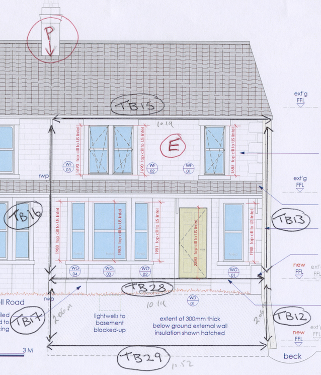
It wasn’t straightforward thinking in the three dimensions necessary to identify all the Thermal Bridges - I invariable kept missing them. We finally finished up with 27. Of these 9 were beneficial with a negative psi value - in a Passive House this is inevitable because of the requirement to use external dimensions. The figure below shows the Thermal Bridges on the problematic front elevation. TB16 and TB17 are calculated separately because TB16 is a loss to ambient air and TB17 is below ground. TB28 is the Thermal Bridge where the below ground external insulation switches to the above ground internal insulation. For completeness TB15 is the horizontal bridge where the front elevation meets the first floor ceiling (it’s a cold roof design). TB13 is the vertical bridge where the front elevation meets the end cavity wall (to ambient air) TB14 is the same but odd - below ground to the front elevation but to ambient air to the end wall.
It wasn’t straightforward thinking in the three dimensions necessary to identify all the Thermal Bridges - I invariable kept missing them. We finally finished up with 27. Of these 9 were beneficial with a negative psi value - in a Passive House this is inevitable because of the requirement to use external dimensions. The figure below shows the Thermal Bridges on the problematic front elevation. TB16 and TB17 are calculated separately because TB16 is a loss to ambient air and TB17 is below ground. TB28 is the Thermal Bridge where the below ground external insulation switches to the above ground internal insulation. For completeness TB15 is the horizontal bridge where the front elevation meets the first floor ceiling (it’s a cold roof design). TB13 is the vertical bridge where the front elevation meets the end cavity wall (to ambient air) TB14 is the same but odd - below ground to the front elevation but to ambient air to the end wall.
Thermal bridge analysis using Psi-Therm showed very large losses if unmitigated of up to over 700kW/a per bridge (Note the house is approx 150 sq m so the worst single Thermal Bridge could add over 4.0 kW/a per metre towards the 15.0 kW/a Passive House total limit and we had 18 Thermal Bridges with a positive psi!)
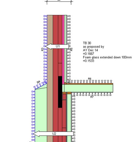
Thermal Bridge mitigation meant changing the designs and losing more space - 100mm of additional insulation (PIR) was added to all basement elevations. Insulated returns of at least 1metre were added to the ground and first floors. Below is the proposed mitigation for TB28 (note TB30 is the rebuilt Bay Window element of TB28). 100mm of PIR on the basement wall and brick replaced by Foam Glass is key places)
Thermal Bridge mitigation meant changing the designs and losing more space - 100mm of additional insulation (PIR) was added to all basement elevations. Insulated returns of at least 1metre were added to the ground and first floors. Below is the proposed mitigation for TB28 (note TB30 is the rebuilt Bay Window element of TB28). 100mm of PIR on the basement wall and brick replaced by Foam Glass is key places)
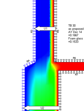
The resulting temperatures through the elements - you can see how the external insulation plinth helps.
Psi-Therm was bought after trying to use the free Therm package - I just found Psi Therm much faster to use.
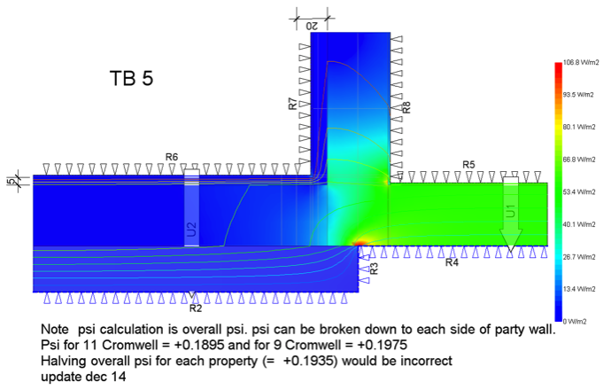
One element of the thermal modelling software that is useful for giving clues for how to reduce a problematic thermal bridge is the heat flux display. The figure below shows the heat flux display where the externally insulated rear wall meets the neighbour (it’s the rear equivalent of TB16 in a figure above). The red shows the highest flux - not avoidable but additional insulation on the internal faces could reduce the Psi for 11 Cromwell further. For information this Thermal Bridge increases the Annual Heating total by 74kW/a so it probably still needs more thought!